Calibration Guide
Overview
The calibration of a joystick is crucial for precise and accurate control, as it ensures that joystick movements are correctly transmitted to the aircraft software. Firstly, all axes of the sidestick, rudder and tiller must be calibrated in Windows 11. This is followed by assignment and calibration in the A320 software (e.g. ProSimA320).
Calibration in Windows
To calibrate a joystick in Windows 11, you can follow the steps below:
- Opening the control panel
Press the 'Windows key' and enter "Control Panel" in the search field. Click on the "Control Panel" app. - Open game controller settings
In the Control Panel, make sure that the view is set to "Large icons" or "Small icons". Search for and click on "Devices and printers". - Select joystick
Your joystick should be displayed in the list of devices under "Devices". Right-click on the icon of your joystick and select "Game controller settings". - Open properties
Your joystick should be listed in the "Game controller" window. Select it and click on "Properties". - Start calibration
In the properties window, click on the "Settings" tab. Click on the "Calibrate" button. - Calibration wizard
The calibration wizard opens. Click on "Next" and follow the instructions on the screen to complete the calibration. This usually involves moving the joystick to different positions and pressing the buttons. - Finalise
Once the calibration is complete, click on "Finish". On the "Test" tab, check whether the joystick is calibrated correctly by testing the axes and buttons. - Save and close
Click "OK" to close the properties window and then click "OK" again in the "Game controller" window to finalise the calibration.

BU0836A interface is the USB Controller Card for the left and right sidebase.
Note: The axis of the Tiller is part of the USB controller for the sidestick.
Calibrate axis
In the next step, the axes must be calibrated. We use ProSim as an example. If you are not working with ProSim, please use the installation instructions for your product.
Open ProSim System
Select the Menue "Config", "Configuration" and then "Combined Config". Search for the "Flight Controls" and "Lever".
Set primary axes
The following axes must be set:
- CPT Sidestick Roll
- CPT Sidestick Pitch
- CPT Tiller
- CPT Rudders
- CPT Brake Left
- CPT Brake Right
- FO Sidestick Roll
- FO Sidestick Pitch
- FO Tiller

Note: If the rudder pedals are coupled, the FO side does not need to be calibrated any further.
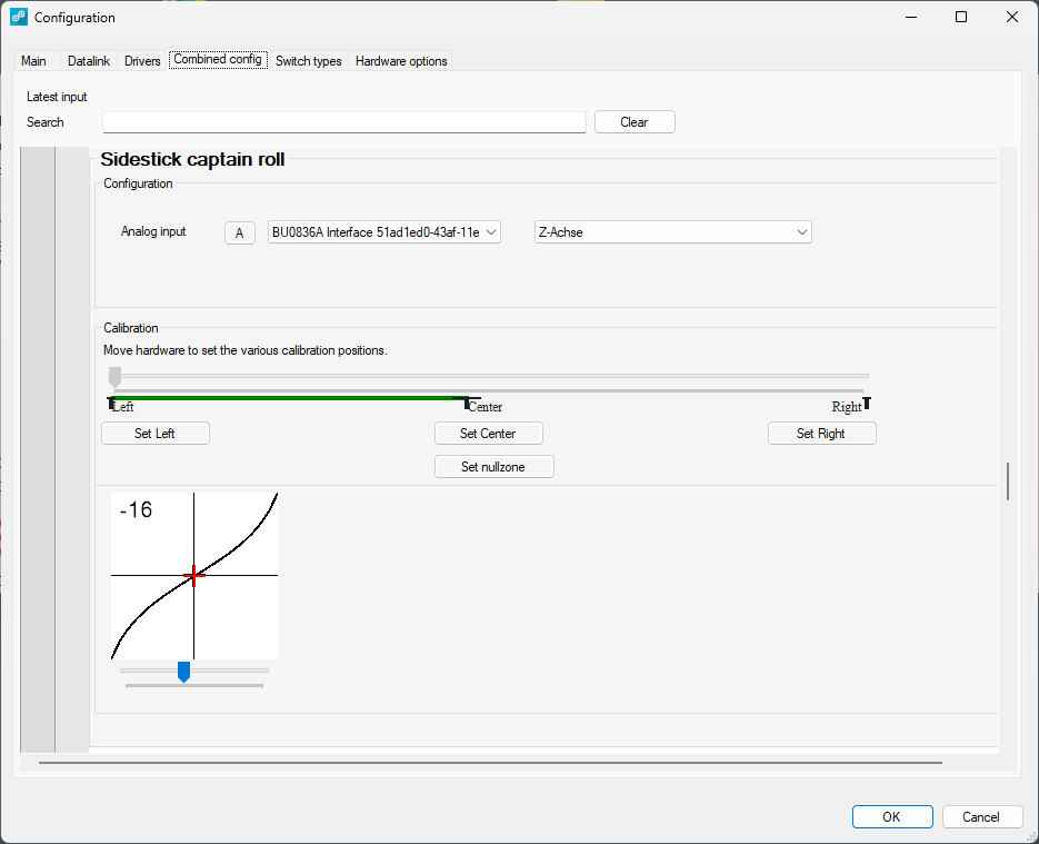
Example: Setting "CPT Sidestick Roll"
- Find the right axis
Press "A" and then move the axis to the right or up. The last axis pressed is automatically assigned. - Finding the right direction of movement
If the green indicator moves in the wrong direction, select "Reverse" from the list. - Define end points
Move the axes to one end position and press the respective button.

The zero zone on game controllers refers to the area around the centre position of a joystick or analogue stick in which no movement is registered. This helps to avoid unwanted inputs due to minimal or unintentional pressure by ignoring small deviations.
Set null zones
Null zone
Ensure that slight movements do not cause the axle to leave the null zone. The same applies to the hands-free return to the neutral position.

If "Calibration Error" messages appear in the ECAM during the flight, the null zone has not been defined correctly.
Sensitivity
It controls the sensitivity of the control signals and is used to adjust the response behaviour.

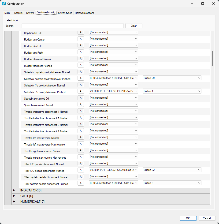
Assign buttons
The following buttons must be assigned:
- CPT Sidestick PTT
- CPT Sidestick AP disconnect
- CPT Tiller disconnect
- FO Sidestick PTT
- FO Sidestick AP disconnect
- FO Tiller disconnect

Important: Use the "find the right axis"-procedure described above. The buttons selected above may not be the same in your setup.
Other axis
The following axes must then be assigned and calibrated:
- Flaps
- Speedbrakes
- Throttle 1
- Throttle 2
- Trimwheel
Here are some examples for settings:

Important: The positions in the screens may vary from your setup.


Note: With the trim wheel, you may not see a green axis. This is normal. Please carry out the calibration anyway, even if the screen display appears unreasonable.


ADIRS configuration
If your ADIRS panel has no hardware switches for IR1, IR2 and IR3 you will need to set the following configuration.

Windshear
In case you have no WX2 or your simulation software does not support windshear, you can switch it permanently off to avoid consistant ECAM messages like below.


Landing Elevation
Calibrate the Landing Elevation as shown below.

Please make sure that "AUTO" and "-2" is in different positions. It may be the case that you cannot select "-2" according to the panel scale.

If the PRESS MODE SELECTOR Korry does not keep its value please change the button behavior from "Latched" to "Momentary" in the "Switch Types" menue.

Hydraulic issues
If you don't have an aft overhead section with maintenance panel and you receive ECAM message similar to the picture below make sure that the "MAINT"-checkbox in the Skalarki Profiler overhead settings is unchecked.

